Biointerface
Electrodes, chemical or optical sensors and stimulation sites must interact predictably with tissue.
THE ENGINEERING STACK
A power link, sensor, communication path and packaged biointerface must work together under the physical and safety constraints of a specific intended use.
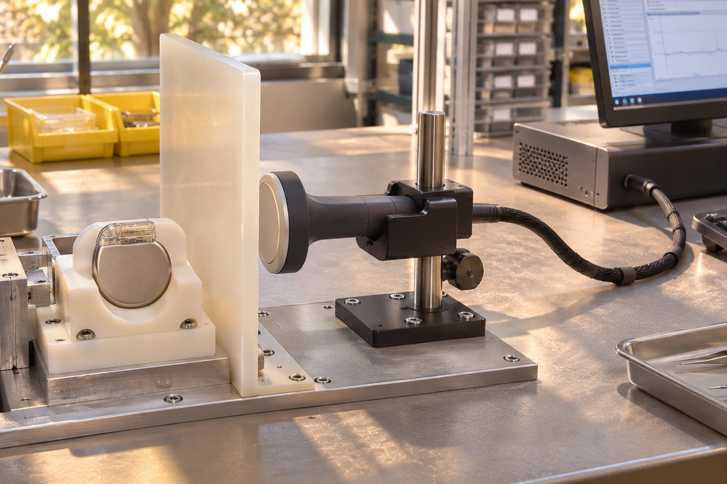
FUNCTIONAL ARCHITECTURE
From tissue-interface physics to secure external tools, the product architecture spans a chain of interdependent choices.
Electrodes, chemical or optical sensors and stimulation sites must interact predictably with tissue.
Coils, acoustic receivers or other transducers provide power within size and exposure constraints.
Low-noise front ends, signal conversion, processing and power management determine the budget.
Link modality, coding, coexistence and authentication determine useful external access.
Feedthroughs, hermetic materials, sterilization and mechanical compliance govern durability.
Chargers, wearables, programmers and clinical workflows are essential system components.
PHYSICAL LINKS
A device architecture follows anatomy, communication needs, exposure constraints and required operating life.
| Modality | Where it fits | Design focus | Explore |
|---|---|---|---|
| Inductive / resonant magnetic | Nearby transmitter with suitable geometry | Alignment, depth, efficiency and heating | Power links |
| Ultrasound | Miniature acoustic receivers and studied deep-tissue routes | Coupling, alignment, anatomy and exposure | Acoustic links |
| RF radio | Data transmission and approved external interfaces | Antenna loading, EMC, coexistence and security | Telemetry |
| Optical / infrared | Specialized short transcutaneous data links | Scattering, positioning and optical safety | Optical links |
LINK ARCHITECTURES
The choice of host changes packaging and connectivity physics, but useful information still depends on an accessible external interface.
IMPLANTED
Placed into tissue or a body cavity for sensing, therapy or physiological interfaces.
Explore chapter →RETAINED
A swallowed livestock bolus designed to remain in the reticulum and report measurements.
Explore chapter →ENGINEERED
Electronics housed inside concrete, equipment or other manufactured structures.
Explore chapter →POWER MODELS
Some implanted transponders are energized by a reader, while other devices have onboard batteries or wireless charging.
Explore chapter →THE SYSTEM DECISION
Signal requirements, implantation depth, intended operating duration, movement, energy availability and external user interaction determine which wireless architecture makes sense. Component benchmarks matter only when translated into useful system performance.
Independent testing must account for electromagnetic compatibility, tissue interactions and secure operating modes. Read those topics in the clinical validation chapter and the linked FDA resources.
System architectureCORE QUESTIONS
How much energy is required at the implant, and under what movement or alignment conditions?
What data must be transmitted, with which timing and failure behavior?
How is biological integrity maintained for the intended duration?